Hardware instructions
Precautions before use
- Make sure the power supply voltage must be 4.5-5.5V. If the power supply exceeds or falls below this range, the machine cannot work normally. If the power supply voltage is too high, the module screen will be damaged.
- Determine whether the serial port level is RS232 or TTL or RS485, and choose according to the requirements in conjunction with the fourth point.
- Pay attention to the interface definition instructions of the power interface socket, and do not connect it wrongly.
Module function interface diagram
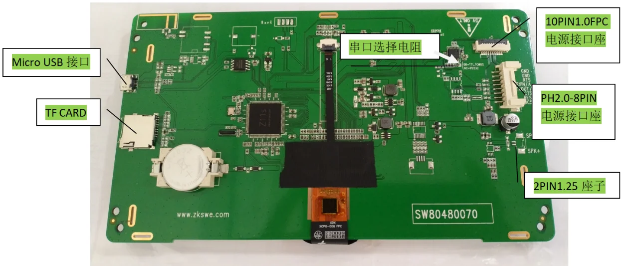

Power interface description
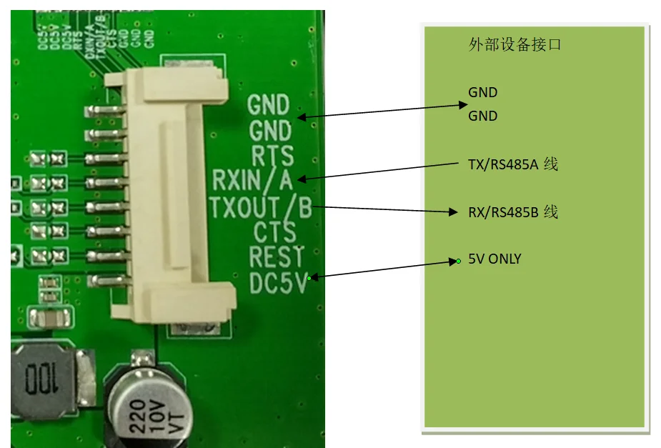
PH2.0-8PIN seat interface definition
| 1PIN | 2PIN |3PIN | 4PIN | 5PIN | 6PIN | 7PIN | 8PIN | | --- | --- | --- | --- |--- | --- |--- | --- | | DC5V | RESET | CTS | TXOUT/B | RXIN/A | RTS | GND | GND |
|DC power input 4.5-5.5V |Module RESET, the default is NC |Flow control CTS |Serial TX or RS485-B. (Connect to external equipment RX/RS485B) |Serial RX or RS485-A (connect to external equipment TX/RS485A) | Flow control RTS| Power ground | Power ground |
10PIN1.0FPC socket interface definition
| 1/2/3PIN | 4PIN | 5PIN | 6PIN | 7PIN | 8/9/10PIN | | --- | --- | --- | --- |--- | --- | | DC5V | RTS | RXIN/A | TXOUT/B | CTS | GND | |DC power input 4.5-5.5V | Flow control RTS | Serial port RX or RS485-A (connect to external device TX/RS485A) | Serial port TX or RS485-B. (Connect to external equipment RX/RS485B) | Flow control CTS | Power ground |
Serial output mode selection
As illustrated
0R resistance is TTL, 0R is not RS232.

The module screen corresponds to the external device interface diagram
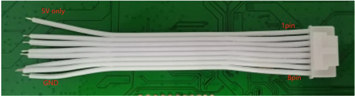
Sample distribution power cord description
The power cord is a white-blue or white-red cord with a single-ended PH2.0-8PIN 10CM buckle. As shown